Learn to Diagnose & Clear P0641 with iCarsoft CR MAX: Fix 5V Reference Circuit Faults
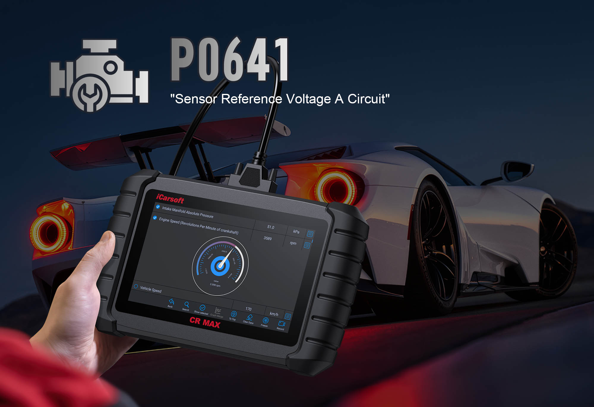
If your Check Engine Light pops on and a scan returns P0641, you’re dealing with a critical issue in your vehicle’s electrical backbone: the 5V reference circuit. This generic OBD-II code stands for “Sensor Reference Voltage A Circuit/Open,” meaning the Engine Control Module (ECM) is detecting unstable, interrupted, or out-of-range voltage in the circuit that powers key sensors—think throttle position sensors (TPS), manifold absolute pressure (MAP) sensors, and oxygen sensors.
These sensors rely on a steady 5V supply to send accurate data to the ECM. When P0641 strikes, sensor readings go haywire, leading to rough idle, hesitation, stalling, or even failed starts. Basic scanners might only label it a “5V fault” but can’t pinpoint where the problem lies. The iCarsoft CR MAX changes that. With its advanced electrical diagnostics, vehicle-specific wiring maps, and real-time voltage tracking, it turns P0641 from a mystery into a fixable issue. Let’s break down how to use it.
1. Understand P0641—The 5V Reference Circuit Basics
Before diving into diagnostics, let’s demystify the system behind P0641 and why it’s critical to your vehicle’s performance:
What the 5V Reference Circuit Does
The ECM generates a consistent 5V direct current (DC) that acts as a “power backbone” for multiple analog sensors. Each sensor (e.g., TPS, MAP) modifies this 5V signal to communicate specific engine conditions:
-
A TPS sends 0.5V when the throttle is closed and 4.5V at wide-open throttle.
-
A MAP sensor adjusts voltage based on intake manifold pressure (lower voltage = lower pressure).
-
Oxygen sensors use 5V to power their internal heaters and transmit air-fuel ratio data.
The ECM uses these modified signals to fine-tune fuel injection, ignition timing, and airflow—without steady 5V, these adjustments go wrong.
Why P0641 Triggers
The code activates when the ECM detects three key issues with the 5V circuit:
Voltage Out of Range
Voltage drops below 4.5V (too weak to power sensors) or rises above 5.5V (risk of damaging sensors). This is the most common trigger, often caused by shorts or failing components.
Complete Circuit Open
No voltage reaches the sensors—usually from a broken wire, disconnected connector, or blown fuse. This causes sensors to send “0V” signals, which the ECM flags as a fault.
Erratic Voltage Fluctuations
Voltage spikes or drops randomly (e.g., 5V → 2V → 5V in 1 second). This confuses the ECM, leading to inconsistent sensor readings and performance issues.
Key Symptoms of P0641
Don’t Ignore These Warning Signs
-
Rough Idle or Misfires: The ECM gets bad sensor data, so it can’t balance fuel and air correctly—you’ll feel shaking or “sputtering” at idle.
-
Hesitation or Lack of Power: During acceleration, the TPS/MAP sensors send incorrect signals, causing the engine to lag or struggle to reach higher RPMs.
-
Stalling: Especially at low speeds or stops—without reliable 5V, the ECM can’t adjust fuel delivery fast enough to keep the engine running.
-
Secondary Fault Codes: P0641 often triggers related codes like P0120 (TPS Circuit Malfunction), P0130 (O2 Sensor Circuit), or P0106 (MAP Sensor Range/Performance).
-
Hard Starting: The ECM can’t use sensor data to optimize the air-fuel mixture for startup—you may need multiple cranks to get the engine running.
Common Causes of P0641
1. Shorted Sensor (Most Common)
A failing TPS, MAP, or O2 sensor can “short” the 5V circuit—its internal wiring crosses, dragging voltage down below 4.5V. This is especially common in high-mileage vehicles (100,000+ miles) where sensors wear out.
2. Damaged Wiring
Frayed insulation (from rubbing against hot engine parts), rodent bites, or corrosion creates shorts (voltage leaks) or opens (broken connections). Wiring near the exhaust manifold or alternator is most at risk.
3. Bad Connectors
Water intrusion (from rain or car washes) or corrosion (green/white buildup) on connector pins breaks the 5V flow. Sensors with exposed connectors (e.g., MAP sensors on the intake manifold) are prone to this.
4. ECM Malfunction (Rare)
The ECM’s internal voltage regulator fails, so it can’t maintain a steady 5V. This only happens if the ECM is damaged (e.g., from a voltage spike) and usually triggers additional codes like P0606 (ECM Internal Control Module Fault).
5. Aftermarket Electronics
Improperly installed stereos, LED lights, or GPS devices that tap into the 5V circuit siphon power or cause voltage spikes. DIY “quick fixes” (e.g., using wire taps) are a major culprit here.
2. Why iCarsoft CR MAX Is Perfect for P0641
P0641 demands precision—basic scanners only read the code but can’t isolate the problem. The iCarsoft CR MAX is built for electrical diagnostics, with features that cut through guesswork:
3. Step-by-Step: Diagnose P0641 with iCarsoft CR MAX
Follow this structured process to find and fix P0641—no prior electrical experience needed. The CR MAX guides you every step of the way:
-
Step 1: Connect the CR MAX & Confirm P0641
-
Plug the CR MAX into your vehicle’s OBD-II port (usually under the dashboard) and power it on.
-
Turn the ignition to “On” (don’t start the engine) and wait for the scanner to initialize.
-
Select Auto VIN Detection (faster and more accurate) or manually enter your vehicle’s make/model/year.
-
Navigate to Engine > Fault Codes > Read Codes to confirm P0641 is present. Tap Code Details for vehicle-specific triggers (e.g., “GM: 5V Reference Below 4.2V for 3 Consecutive Seconds”).
-
Note any secondary codes (e.g., P0120)—these hint at which sensor is causing the 5V issue.
-
Step 2: Monitor 5V Voltage in Real Time
-
Go to Engine > Live Data > Electrical System and select these parameters (tap “Add to Favorites” for easy access):
-
“5V Reference Voltage” (target range: 4.5V–5.5V)
-
“TPS Voltage” (should be 0.5V–4.5V, depending on throttle position)
-
“MAP Sensor Voltage” (usually 0.9V–4.5V, depending on engine load)
-
“O2 Sensor Heater Voltage” (should be ~5V if the heater is active)
-
Start the engine and let it idle for 2 minutes. Watch the 5V Reference Voltage:
-
P0641 Confirmed: Voltage dips below 4.5V, jumps above 5.5V, or fluctuates by more than 0.2V.
-
Normal 5V (4.5V–5.5V): The issue is intermittent—skip to Step 3 to check for loose connections.
-
Optional: Gently press the throttle while monitoring TPS voltage—if 5V drops when you accelerate, the TPS may be shorted.
-
Step 3: Inspect Wiring & Connectors
-
Turn off the ignition and disconnect the CR MAX (temporarily) to access the 5V circuit components.
-
Open the CR MAX app’s Component Location (under Special Functions) to find all 5V-connected sensors (varies by vehicle, but TPS and MAP are standard).
-
Visually inspect the circuit for these issues:
-
Frayed Wiring: Look for exposed copper near hot parts (exhaust, alternator) or moving components (belts).
-
Corroded Connectors: Check sensor pins for green/white buildup—focus on the TPS, MAP, and O2 sensors.
-
Loose Harnesses: Gently wiggle wiring harnesses—if the 5V voltage jumped during Step 2 when you moved a harness, this is the issue.
-
Clean corroded pins with electrical contact cleaner and a small brush. Reconnect loose connectors firmly.
-
Reconnect the CR MAX and recheck 5V voltage—if it’s now stable, you fixed the problem!
-
Step 4: Isolate the Faulty Sensor
-
If wiring/connectors look good, a sensor is likely shorting the 5V circuit. Keep the CR MAX on the 5V Reference Voltage live data screen.
-
Turn the ignition to “On” (engine off) and disconnect one sensor at a time (start with the sensor linked to a secondary code, e.g., TPS for P0120):
-
Voltage Stabilizes (4.5V–5.5V): The disconnected sensor is faulty—mark it for replacement (Step 6).
-
Voltage Still Bad: Reconnect the sensor and test the next one (e.g., MAP sensor if TPS was good).
-
Use the CR MAX’s Notes feature (under Settings) to log which sensor fixed the voltage—this avoids forgetting later.
-
Step 5: Test Circuit Continuity & Resistance
-
If no sensor is the issue, hidden wiring damage is the culprit. Go to Special Functions > Electrical Tests > Multimeter and set it to “Resistance (Ω).”
-
Use the CR MAX’s wiring diagram to find the 5V reference wire (usually labeled “5V REF” or colored red/white) and a chassis ground (metal part of the engine bay).
-
Run two key tests:
-
Resistance to Ground: Touch one multimeter probe to the 5V wire and the other to ground. Infinite resistance (OL on the screen) = good; any reading (e.g., 10Ω) = shorted wire (needs repair).
-
Continuity Between ECM & Sensor: Touch one probe to the 5V wire at the ECM connector and the other to the 5V pin on the sensor connector. <5Ω = good; infinite resistance = broken wire (replace the harness section).
-
Repair damaged wires with heat-shrink butt connectors (match the wire gauge to the original) and recheck 5V voltage.
-
Step 6: Check for ECM Issues
-
If all wiring and sensors check out, the ECM’s voltage regulator may be faulty. Navigate to Special Functions > ECM Tests > 5V Regulator Test.
-
Follow the on-screen prompts: the CR MAX will command the ECM to output 5V and measure it directly at the ECM’s 5V pin (you may need to access the ECM connector—use the wiring diagram for location).
-
Results:
-
4.5V–5.5V: ECM is good—double-check wiring/sensors for missed damage (e.g., a tiny fray in the 5V wire).
-
Outside Range (<4.5V or >5.5V): ECM’s internal regulator is bad—this requires professional repair or replacement (the CR MAX can link you to certified ECM shops).
-
Step 7: Repair & Clear P0641
-
Replace Faulty Sensors: Use the CR MAX’s Part Lookup (under Special Functions) to find OEM sensors (e.g., Denso TPS for Toyota, Bosch MAP for GM)—aftermarket sensors may not work with the 5V circuit.
-
Fix Wiring: Splice damaged sections with matching-gauge wire and heat-shrink tubing; replace corroded connectors with OEM parts.
-
Clear the Code: Reconnect the CR MAX, go to Engine > Fault Codes > Clear Codes, and delete P0641 and any secondary codes.
-
Step 8: Verify the Fix
-
Take a 30-minute test drive that includes idle, acceleration, and highway speeds—this replicates real-world conditions.
-
Use the CR MAX’s Data Logging (under Live Data) to record 5V reference and sensor voltages during the drive. Save the log for future reference.
-
After driving, re-scan for codes: No P0641 + stable 5V (4.5V–5.5V) = success!
-
If P0641 returns, repeat Step 4–5—you may have missed a shorted sensor or hidden wiring damage.
4. How to Prevent P0641 from Coming Back
The CR MAX isn’t just for fixes—it helps you avoid future 5V circuit issues. Add these steps to your vehicle maintenance routine:
Proactive P0641 Prevention
-
Quarterly Electrical Scans: Run System Checks > Electrical Health on the CR MAX every 3 months. This monitors 5V stability and catches minor issues (e.g., slightly corroded connectors) before they trigger P0641.
-
Protect Wiring: Secure loose harnesses with zip ties away from heat sources (exhaust, radiator) and moving parts (belts, pulleys). Use split loom tubing for extra insulation on exposed 5V wires.
-
Dielectric Grease: Apply a small amount of dielectric grease to sensor connectors during replacement. This blocks moisture and corrosion, extending the life of the 5V circuit.
-
Avoid Shoddy Add-Ons: Have aftermarket electronics (stereos, LED bars) installed by professionals. Never tap into the 5V reference circuit for DIY mods—use dedicated power sources instead.
-
ECM Software Updates: Use the CR MAX’s One-Key Upgrade to install manufacturer ECM patches. Some P0641 cases are caused by outdated software that misinterprets 5V signals—updates fix this for free.
-
High-Mileage Sensor Checks: For vehicles over 100,000 miles, use the CR MAX to test TPS/MAP/O2 sensor voltages during regular oil changes. Replace sensors that show erratic readings (even if no code is present).
5. Conclusion
P0641 Is Fixable—With the Right Tool
P0641 might sound intimidating (electrical issues scare many DIYers), but it’s a straightforward problem with the iCarsoft CR MAX. Its ability to track 5V voltage in real time, isolate faulty sensors, and pull vehicle-specific wiring diagrams turns guesswork into precision.
No more wasting money on unnecessary sensors or expensive dealer visits—you can diagnose and fix P0641 in an afternoon. Whether you’re working on a family sedan, pickup truck, or European luxury vehicle, the CR MAX gives you the confidence to resolve electrical faults like a pro.
Don’t let P0641 leave you stranded or damage other components (e.g., a shorted sensor can fry the ECM). Grab the iCarsoft CR MAX, follow the steps above, and get your vehicle’s 5V reference circuit—and performance—back on track.