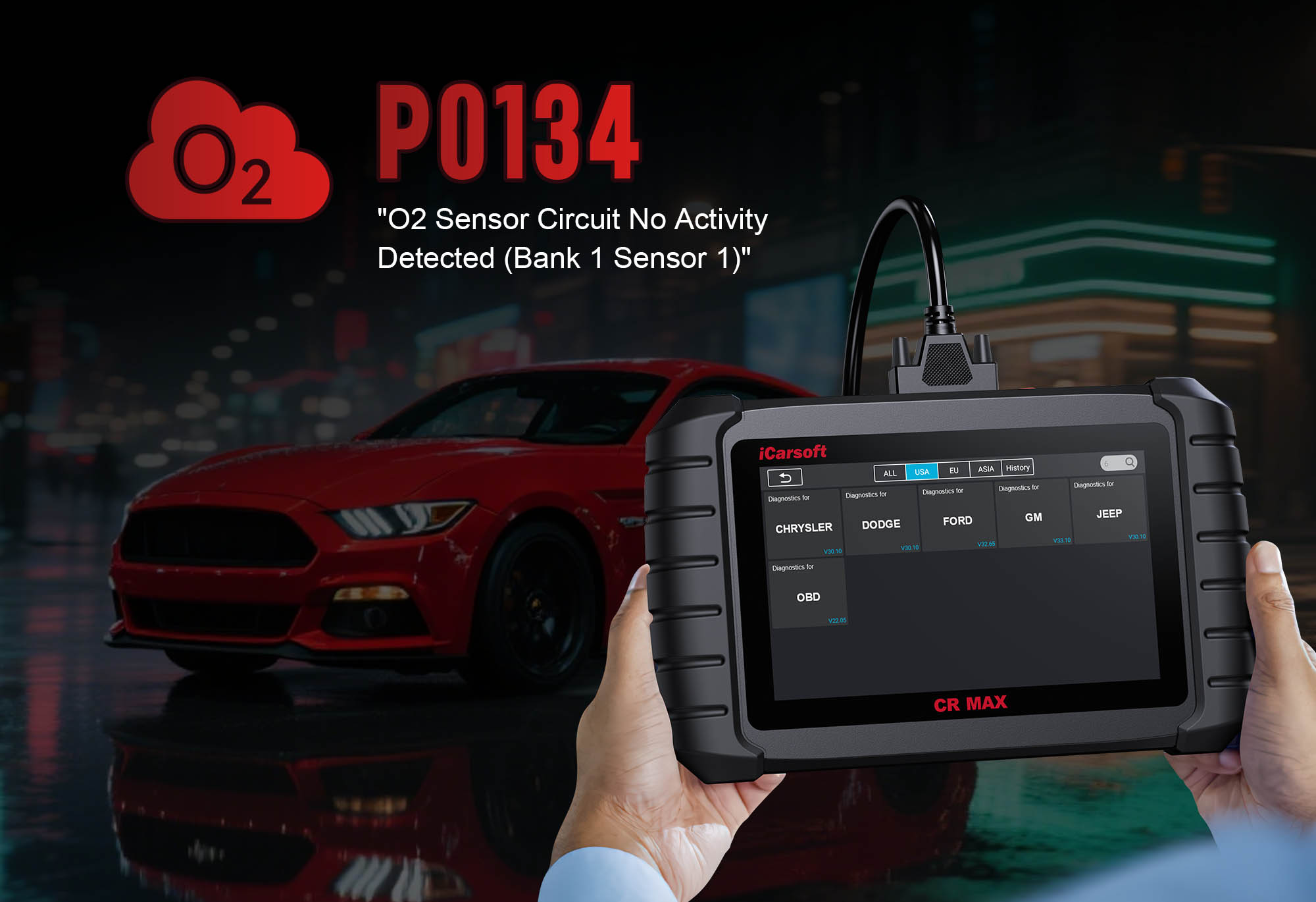
Diagnose & Clear P0134 with iCarsoft CR MAX: Fix Oxygen Sensor Inactivity
If your Check Engine Light turns on and a scan reveals P0134, your vehicle is alerting you to a problem with its critical oxygen sensor system. This generic OBD-II code stands for “Oxygen Sensor Circuit No Activity Detected (Bank 1, Sensor 1),” meaning the upstream oxygen sensor on Bank 1 isn’t sending valid voltage signals to the Engine Control Module (ECM).
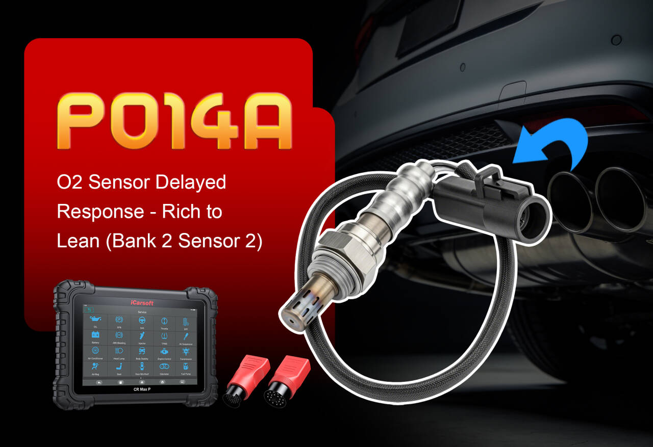
The upstream oxygen sensor (Bank 1, Sensor 1) is critical for regulating fuel efficiency and emissions. Positioned before the catalytic converter, it monitors unburned oxygen in exhaust gases, sending voltage fluctuations (0.1V for lean mixtures to 0.9V for rich mixtures) to the ECM. This data allows the ECM to adjust fuel injection for optimal combustion. When P0134 occurs, the sensor’s signal is flat or nonexistent, leading to poor fuel economy, rough idle, and increased emissions.
Basic scanners may only confirm “no sensor activity” but can’t identify whether the issue is a faulty sensor, damaged wiring, or power problems. The iCarsoft CR MAX solves this with advanced sensor testing, real-time voltage tracking, and vehicle-specific diagnostics. Let’s walk through how to use this tool to fix P0134.
1. Understanding P0134: Causes & Symptoms
To diagnose P0134 effectively, start by breaking down key details about the code, normal sensor behavior, and what triggers the fault:
What “Bank 1, Sensor 1” Means
The code’s “Bank 1, Sensor 1” label is critical for locating the faulty component:
-
Bank 1: Refers to the cylinder bank that contains cylinder #1 (check your vehicle’s service manual for cylinder numbering—e.g., front cylinder on inline engines, left bank on V6/V8 engines).
-
Sensor 1: The upstream sensor, mounted before the catalytic converter. This sensor is responsible for fine-tuning the air-fuel mixture (unlike Sensor 2, which monitors catalytic converter efficiency).
Normal Oxygen Sensor Behavior
A healthy upstream oxygen sensor (Bank 1, Sensor 1) has distinct voltage patterns—deviations from this indicate P0134:
-
Voltage Range: Switches between 0.1V (lean air-fuel mixture: too much oxygen, too little fuel) and 0.9V (rich mixture: too little oxygen, too much fuel).
-
Fluctuation Speed: 5–10 cycles per second when the engine is warm (operating temperature) and under load (e.g., acceleration).
-
Heater Activation: The sensor’s internal heater (powered by 12V) warms it to 300°C+ within 1–2 minutes of starting—this is required for accurate readings (cold sensors don’t generate signals).
Common Symptoms of P0134
Warning Signs to Watch For
-
10–15% Lower Fuel Economy: Without sensor data, the ECM defaults to a “safe” rich mixture (more fuel than needed), wasting gas.
-
Rough Idle or Hesitation: The ECM can’t adjust fuel delivery in real time, leading to uneven combustion at idle or lag during acceleration.
-
Failed Emissions Tests: Unregulated air-fuel mixtures increase harmful emissions (hydrocarbons, carbon monoxide), causing test failures.
-
Secondary Fault Codes: P0134 often pairs with P0171 (System Too Lean, Bank 1) or P0172 (System Too Rich, Bank 1) due to the ECM’s incorrect fuel adjustments.
-
Illuminated Check Engine Light: The first and most consistent sign—use the CR MAX to confirm P0134 (never ignore this, as rich mixtures can damage the catalytic converter).
Root Causes of P0134
P0134 stems from issues that stop the sensor from generating or transmitting valid signals. Below are the most frequent causes, ordered by likelihood:
1. Faulty Oxygen Sensor (Most Common)
Sensors wear out after 80,000–100,000 miles:
-
Internal sensing element failure (can’t generate voltage from exhaust oxygen).
-
Heater element burnout (sensor never reaches operating temperature).
-
Contamination (oil, carbon, or coolant poisons the sensor—common if the engine burns oil or has a coolant leak).
2. Damaged Wiring/Connectors
The sensor’s wiring harness (usually 4–5 wires) is vulnerable to damage:
-
Frayed or cut wires (from rubbing against hot exhaust parts or road debris).
-
Corroded connectors (moisture or road salt causes green/white buildup on pins).
-
Loose terminals (vibration over time disconnects the sensor from the ECM).
3. Heater Circuit Issues
The sensor’s heater needs 12V power to warm up—without it, the sensor stays cold and inactive:
-
Blown oxygen sensor heater fuse (check your vehicle’s fuse box—labeled “O2 Heater” or “Sensor 1”).
-
Failed heater relay (prevents power from reaching the sensor’s heater).
-
Broken heater wire (cuts power to the internal heater element).
4. Exhaust Leaks
Leaks before the sensor draw in outside air, flooding the sensor with oxygen:
-
Loose or damaged exhaust manifold gaskets (common on high-mileage vehicles).
-
Holed exhaust downpipe (from rust or impact).
-
Cracked exhaust manifold (heat cycles cause metal fatigue).
The extra oxygen tricks the sensor into sending a constant “lean” signal (0.1V) or no signal at all.
5. ECM Malfunction (Rare)
The ECM fails to send power to the sensor or process its signals:
-
Internal ECM circuitry failure (can’t read sensor voltage).
-
Outdated ECM firmware (misinterprets normal sensor activity as “no signal”).
This only happens if other causes are ruled out—usually paired with ECM-related codes like P0606.
2. Why iCarsoft CR MAX Is Ideal for P0134
Basic scanners only confirm “no sensor activity,” but the iCarsoft CR MAX digs deeper—its features are tailored to oxygen sensor diagnostics, eliminating guesswork and unnecessary part swaps:
3. Step-by-Step: Diagnose P0134 with iCarsoft CR MAX
Follow this structured process to pinpoint the root cause of P0134—no prior oxygen sensor experience needed. The CR MAX guides you every step of the way:
-
Step 1: Connect the CR MAX & Confirm P0134
-
Plug the CR MAX into your vehicle’s OBD-II port (under the dashboard) and power it on.
-
Turn the ignition to “On” (don’t start the engine) and wait for the scanner to initialize.
-
Select Auto VIN Detection (faster and more accurate) or manually enter your vehicle’s make/model/year.
-
Navigate to Engine > Fault Codes > Read Codes to confirm P0134 is present. Tap Code Details for vehicle-specific triggers (e.g., “GM: O2 Sensor Bank 1, Sensor 1 No Voltage Change for 45 Seconds”).
-
Note secondary codes (e.g., P0171, P0172)—these hint at related issues (e.g., exhaust leaks causing lean/rich conditions).
-
Step 2: Monitor Live Sensor Voltage
-
Go to Engine > Live Data > Oxygen Sensors and select:
-
“O2 Sensor Voltage (Bank 1, Sensor 1)”
-
“O2 Sensor Heater Status” (shows “Active” or “Inactive”)
-
Start the engine and let it warm to operating temperature (10–15 minutes, until the coolant temperature gauge reaches the middle mark):
-
P0134 Confirmed: Voltage stays flat at ~0.45V (no fluctuations) or reads 0V/5V (no signal).
-
Intermittent Issue: Voltage fluctuates normally but drops out occasionally (check wiring/connectors next).
-
Heater Issue: “O2 Sensor Heater Status” stays “Inactive” (skip to Step 4 to test the heater circuit).
-
Step 3: Locate & Inspect the Sensor
-
Use the CR MAX’s Component Location tool (under Special Functions) to find Bank 1, Sensor 1—most are mounted on the exhaust manifold or downpipe (look for a small, cylindrical sensor with a wiring harness).
-
Visually inspect the sensor and wiring for damage:
-
Sensor Damage: Oil/carbon buildup on the tip, dents, or a broken connector.
-
Wiring Issues: Frayed insulation, cuts, or wires rubbing against hot exhaust parts (look for melted plastic).
-
Connector Problems: Corrosion (green/white deposits), bent pins, or loose terminals (disconnect the connector and check inside).
-
Clean corroded connectors with electrical contact cleaner—if voltage stabilizes after cleaning, you’ve fixed the issue!
-
Step 4: Test the Heater Circuit
-
Navigate to Special Functions > Engine > Oxygen Sensor Tests > Heater Circuit Test—the CR MAX will guide you through three key checks:
-
Voltage Check: With the engine running, the tool measures voltage at the sensor’s heater pins (should read 12V). No voltage = blown fuse/relay or broken wire.
-
Resistance Test: Turn off the engine, disconnect the sensor, and touch the CR MAX’s multimeter probes to the heater pins. Normal range: 5–15Ω. 0Ω = shorted heater; infinite Ω = burned-out heater.
-
Fuse/Relay Check: Use the tool’s Fuse Location guide to find the O2 heater fuse (usually in the engine bay fuse box). Test the fuse with the CR MAX’s built-in multimeter—blown fuses need replacement.
-
Repair heater circuit issues (replace fuse/relay, splice broken wires) before moving to Step 5—cold sensors can’t generate signals, even if the sensing element is good.
-
Step 5: Check for Exhaust Leaks
-
Exhaust leaks before the sensor are a common hidden cause of P0134. With the engine running (and vehicle on jack stands, if needed):
-
Spray soapy water on exhaust connections near the sensor (manifold gaskets, downpipe flanges, welds).
-
Bubbles forming = leak—mark the spot and turn off the engine.
-
Inspect for cracks in the exhaust manifold (use a flashlight to check hard-to-see areas).
-
Repair small leaks with exhaust sealant; replace gaskets or damaged pipes for larger leaks. Recheck sensor voltage after repairs—leaks often mimic “dead sensor” behavior.
-
Step 6: Run a Sensor Response Test
-
Go to Special Functions > Engine > Oxygen Sensor Tests > Response Test—this test verifies if the sensor can still react to air-fuel changes:
-
Start the engine and let it idle—voltage should drop to 0.1V–0.2V (lean mixture).
-
Rev the engine to 2000 RPM and hold it—voltage should spike to 0.8V–0.9V (rich mixture).
-
Release the throttle—voltage should return to 0.1V–0.2V.
-
Results:
-
No Reaction: Sensor is dead—needs replacement (Step 7).
-
Normal Reaction: Issue is intermittent (check for loose wiring or connector corrosion).
-
Step 7: Repair & Clear P0134
-
Replace the Oxygen Sensor:
-
Use the CR MAX’s Part Lookup (under Special Functions) to find the correct OEM sensor (e.g., Bosch 13701 for Honda, Denso 234-4626 for Toyota). Ensure it matches your vehicle’s sensor type (4-wire, 5-wire—check the old sensor).
-
Disconnect the battery (negative terminal) to avoid electrical shorts.
-
Use an oxygen sensor socket to remove the old sensor; apply anti-seize compound to the new sensor’s threads (avoid getting compound on the tip).
-
Tighten the new sensor to factory specs (usually 18–22 ft-lbs) and reconnect the wiring.
-
Fix Remaining Issues: Repair wiring (splice with heat-shrink connectors) or exhaust leaks (replace gaskets) if needed.
-
Clear the Code: Reconnect the CR MAX, go to Engine > Fault Codes > Clear Codes, and delete P0134 and any secondary codes.
-
Step 8: Verify the Fix
-
Take a 30-minute test drive that includes idle, acceleration, and highway speeds—this ensures the sensor works under real-world conditions.
-
Use the CR MAX’s Data Logging (under Live Data) to record “O2 Sensor Voltage (Bank 1, Sensor 1)” during the drive. Save the log to review later.
-
After driving, re-scan for codes: No P0134 + consistent 0.1V–0.9V fluctuations = success!
-
If P0134 returns, repeat Step 4–5—you may have missed a heater circuit issue or small exhaust leak.
4. Preventing P0134 Recurrence
The CR MAX isn’t just for fixing P0134—it helps you maintain healthy oxygen sensors and avoid future faults. Add these steps to your vehicle maintenance routine:
Proactive P0134 Prevention Tips
-
Replace Sensors Proactively: Use the CR MAX’s Maintenance Reminder to schedule oxygen sensor replacement every 80,000–100,000 miles. This avoids sudden failures and keeps fuel economy high.
-
Use Quality Fuel: Top-tier gasoline (e.g., Chevron, Shell) has fewer impurities that cause carbon buildup on sensor elements. The CR MAX’s Fuel Trim Data can alert you to buildup (consistently lean/rich readings).
-
Check Oil Consumption: Excessive oil burning poisons oxygen sensors. Use the CR MAX to monitor “Short-Term Fuel Trim” (STFT)—consistently high STFT (+10%+) may indicate oil entering the combustion chamber (check for blue exhaust smoke).
-
Inspect Wiring Quarterly: During oil changes, check the sensor’s wiring for damage. Secure loose harnesses with zip ties away from hot exhaust parts—use split loom tubing for extra protection.
-
Update ECM Software: Use the CR MAX’s One-Key Upgrade to install manufacturer ECM patches. Some P0134 cases are caused by outdated software that misinterprets normal sensor activity—updates fix this for free.
-
Test Heater Circuits Annually: Run the CR MAX’s Heater Circuit Test once a year to catch fuse/relay issues before they cause P0134.
5. Conclusion
P0134 Is Fixable—With the Right Tool
P0134’s “no activity” label might seem intimidating, but the iCarsoft CR MAX simplifies diagnosis by turning vague “sensor fault” messages into actionable steps. Its ability to track voltage, test heaters, and guide leak detection eliminates guesswork—saving you from buying unnecessary sensors or paying for expensive dealer visits.
Whether you’re a DIYer fixing your family car or a technician servicing multiple vehicles, the CR MAX ensures you resolve P0134 efficiently. By following the steps above, you’ll restore fuel economy, reduce emissions, and keep your engine running smoothly—all while building confidence in electrical diagnostics.
Don’t let P0134 damage your catalytic converter or waste gas. Grab the iCarsoft CR MAX, diagnose the issue, and get your oxygen sensor system back to working order—your wallet and the environment will thank you.