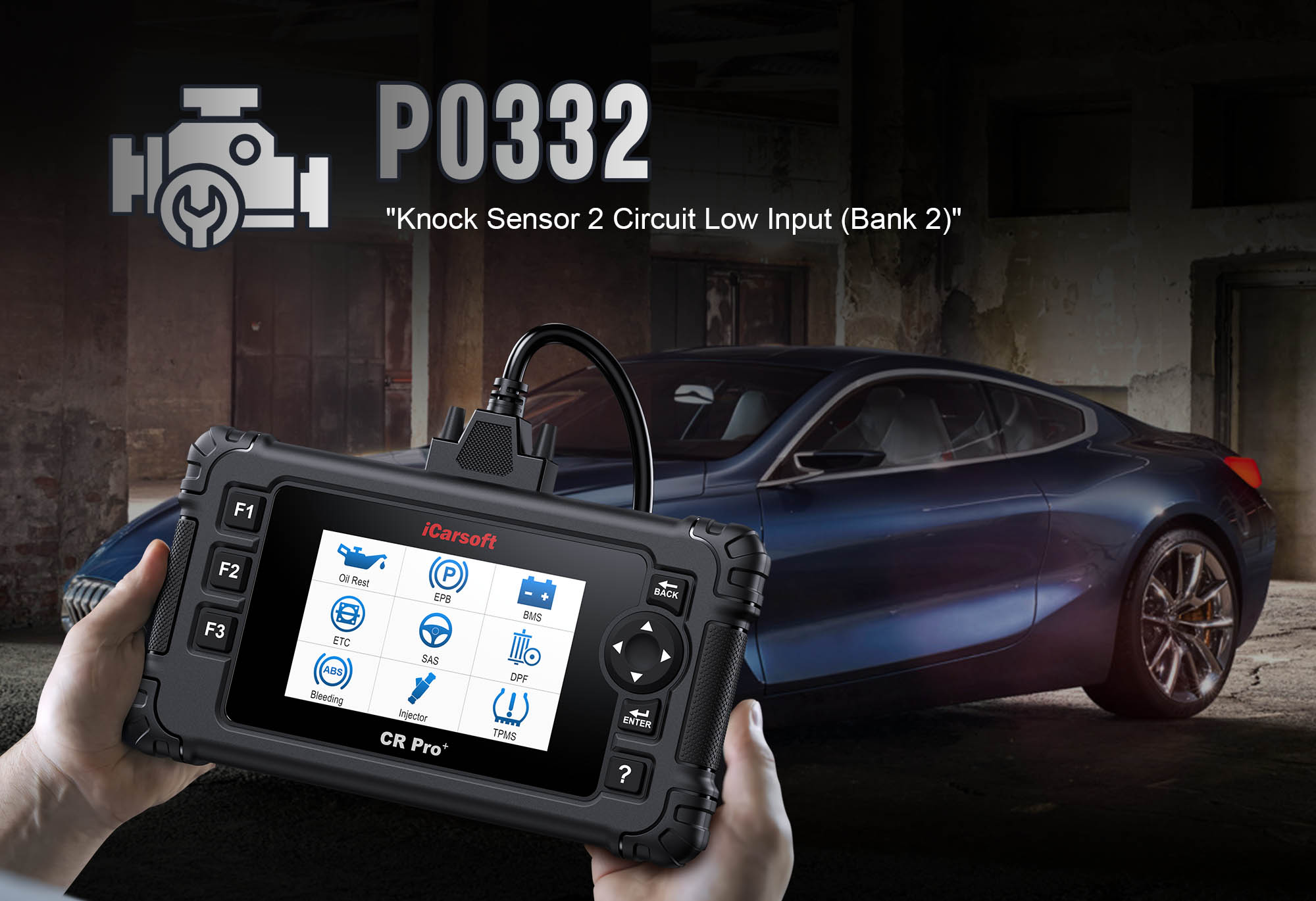
Diagnose & Clear P0332 with iCarsoft CR Pro+: Fix Knock Sensor 2 Circuit Low Input
If your check engine light illuminates and a scan returns P0332, your vehicle’s engine protection system is signaling a critical issue with knock detection. This generic OBD-II code stands for "Knock Sensor 2 Circuit Low Input"—meaning the Engine Control Module (ECM) is receiving an abnormally weak or nonexistent voltage signal from Knock Sensor 2 (KS2), preventing it from detecting harmful engine knock (detonation) in a specific cylinder bank.
Knock sensors are piezoelectric devices that convert engine vibrations (from detonation) into electrical signals. Most V-shaped engines (V6, V8) use two knock sensors: Knock Sensor 1 (KS1) monitors Bank 1, and Knock Sensor 2 (KS2) monitors Bank 2. When detonation occurs—from low-octane fuel, overheating, or timing issues—the sensor sends a voltage spike to the ECM, which retards ignition timing to prevent engine damage. When P0332 occurs, KS2’s signal is too low (often below 0.5V) or absent, leaving Bank 2 unprotected from knock. This risks piston damage, head gasket failure, and reduced engine lifespan.
Basic scanners might only confirm "knock sensor fault" but can’t test KS2’s signal strength or isolate circuit issues. The iCarsoft CR Pro+—with its real-time knock sensor data, circuit continuity testing, and bank-specific diagnostics—solves this. Let’s walk through how to diagnose and resolve P0332.
 iCarsoft CR Pro+ monitoring Knock Sensor 2 (KS2) voltage and frequency for P0332
Understanding P0332: Causes & Key Symptoms
To tackle P0332 effectively, first recognize how weak KS2 signals impact engine safety and performance:
Key Symptoms of P0332
-
Check Engine Light: Illuminates when the ECM detects KS2 voltage below the normal range (e.g., <0.5V) for 3+ consecutive drive cycles.
-
Engine Knock/Detonation: A metallic "pinging" or "knocking" sound from Bank 2 during acceleration (especially under load, like climbing hills or towing).
-
Reduced Power & Acceleration: The ECM may enter "limp mode" to avoid damage, limiting ignition timing and cutting power by 10–20%.
-
Increased Fuel Consumption: Retarded timing (from KS1 overcompensation) reduces combustion efficiency, leading to 5–10% lower MPG.
-
Overheating Risk: Uncontrolled knock increases cylinder temperatures, potentially causing overheating, spark plug damage, or piston scoring.
-
Failed Emissions Tests: Misfires from knock raise hydrocarbon (HC) and carbon monoxide (CO) emissions, leading to test failures.
Common Causes of P0332
|
Cause
|
Description
|
|
Faulty Knock Sensor 2 (KS2)
|
Internal piezoelectric failure (from age, vibration, or heat) causes the sensor to stop generating voltage signals (accounts for ~45% of P0332 cases).
|
|
Damaged KS2 Wiring
|
Frayed, cut, or corroded wires between KS2 and the ECM disrupt signal transmission—common near the engine block (heat damage) or under the hood (rodent chews).
|
|
Loose or Corroded Sensor Connector
|
Poor contact at KS2’s plug (dirt, moisture, or rust) creates a weak electrical connection, leading to intermittent or absent signals.
|
|
Sensor Mounting Issues
|
A loose KS2 (not torqued to manufacturer specs) can’t vibrate properly, resulting in weak signal output; over-tightening damages the sensor’s piezoelectric element.
|
|
ECM Malfunction (Rare)
|
A faulty ECM fails to detect or process KS2’s signal, usually paired with other sensor communication codes (e.g., P0606 for ECM internal fault).
|
|
Engine Mechanical Damage
|
Worn rod bearings, damaged pistons, or loose timing chains in Bank 2 create excessive vibration, overwhelming KS2’s ability to distinguish knock from normal noise.
|
Why iCarsoft CR Pro+ Excels at Diagnosing P0332
The CR Pro+ outperforms basic tools with features tailored to knock sensor and bank-specific diagnostics—critical for pinpointing P0332’s root cause:
Real-Time Knock Sensor Signal Monitoring
Displays KS2’s voltage (in 0.01V increments) and vibration frequency, confirming weak/absent signals (e.g., <0.5V at idle = P0332 trigger) and distinguishing sensor faults from wiring issues.
Bank-Specific Diagnostics
Isolates tests to Bank 2, avoiding confusion with KS1 (Bank 1) and ensuring accurate fault location—no need to guess which sensor is faulty.
Circuit Continuity & Resistance Testing
Identifies breaks, shorts, or high-resistance issues in KS2’s wiring, eliminating guesswork about electrical faults (e.g., broken wire vs. corroded connector).
Vehicle-Specific Sensor Diagrams
Preloaded with color-coded schematics of KS2 locations (usually on the engine block near Bank 2) and wiring paths for 65+ makes (e.g., Ford F-150, Chevrolet Tahoe, Toyota Tundra).
Sensor Torque Specs
Provides exact torque values for mounting KS2 (15–25 ft-lbs, varies by vehicle) to avoid reinstallation errors—critical for proper vibration detection.
Post-Repair Validation
Runs knock simulation tests (tapping the sensor while monitoring voltage) to confirm KS2 and the ECM communicate correctly after fixes—ensures repairs are successful.
Step-by-Step: Diagnose P0332 with iCarsoft CR Pro+
-
1. Connect & Confirm the Code
Plug the CR Pro+ into your vehicle’s OBD-II port (under the dashboard) and power it on.
Select your vehicle via Auto VIN Scan (reads your VIN in 2 seconds) or manual entry (make/model/year/engine).
Navigate to Engine > Fault Codes > Read Codes to confirm P0332. Tap Code Details for vehicle-specific info (e.g., "Ford: Knock Sensor 2 (Bank 2) Voltage = 0.2V – Below Min Threshold").
-
2. Identify Bank 2 & Locate KS2
First, confirm Bank 2 and find KS2 using the CR Pro+’s diagrams:
Bank 2 Identification:
Navigate to Component Location > Engine > Cylinder Banks.
For V-engines: Bank 2 = cylinders farthest from the front (e.g., V8: Bank 1 = 1-2-3-4, Bank 2 = 5-6-7-8; V6: Bank 1 = 1-2-3, Bank 2 = 4-5-6).
KS2 Location:
Go to Component Location > Engine > Sensors > Knock Sensor 2.
The scanner displays a 3D diagram: KS2 is typically mounted on the engine block (between Bank 2 cylinders) or cylinder head, with a 1–2 pin weatherproof connector. Mark the location to streamline testing.
-
3. Monitor Real-Time KS2 Signal
Verify the weak signal with the CR Pro+’s live data:
Start the engine and let it idle for 3 minutes to stabilize (avoid revving—prevents false knock signals).
Navigate to Engine > Live Data > Ignition System and select:
"Knock Sensor 2 Voltage" (normal = 0.5V–1.0V at idle; spikes to 2–5V during knock).
"Knock Sensor 2 Frequency" (normal = 5–15 Hz at idle; increases to 20–30 Hz during detonation).
Accelerate gently to 2,500 RPM (light load) and monitor:
- P0332 Confirmation: Voltage stays <0.5V or frequency remains flat (no response to engine vibration) = weak/absent signal.
- Intermittent Signal: Voltage drops in and out = loose connector or damaged wiring.
-
4. Inspect KS2 Connector & Wiring
Poor connections are a top cause of P0332—check with the CR Pro+’s guidance:
Turn off the engine and disconnect the negative battery terminal (to avoid electrical shorts during testing).
Connector Inspection:
Locate KS2’s connector and disconnect it (press the tab or remove the locking clip). Check for:
- Corrosion (white/green powdery deposits) on terminals.
- Bent, broken, or pushed-in pins.
- Moisture or dirt inside the connector (sign of water intrusion).
Clean corroded terminals with electrical contact cleaner and a small brush; straighten bent pins carefully with a needle-nose plier.
Wiring Inspection:
Follow KS2’s wiring from the connector to the ECM (use the CR Pro+’s wiring diagram). Look for:
- Frayed or cut insulation (common near the engine block, where heat melts wiring).
- Rodent chews (under the hood, near wire harnesses).
- Loose connections at wire harness clips (causes wiring to rub against hot components).
Mark damaged sections for repair; replace wiring with heat-resistant, automotive-grade wire if insulation is severely compromised.
-
5. Test KS2 Circuit Continuity & Resistance
Use the CR Pro+ to rule out wiring faults:
Continuity Test (Signal Path):
Navigate to Special Functions > Electrical Tests > Circuit Continuity.
Connect one test lead to KS2’s signal pin (labeled "SIG" in the connector diagram) and the other to the corresponding ECM pin (found in the CR Pro+’s wiring schematic).
- Normal: 0–1 ohm resistance (signal path is clear).
- Faulty: Infinite resistance = broken wire (repair with heat-shrink butt connectors or replace the harness section).
Resistance Test (Ground Path):
Select Ohmmeter Function and measure resistance between KS2’s ground pin (if equipped, labeled "GND") and the vehicle’s chassis (clean a ground point with sandpaper first).
- Normal: <5 ohms (good ground connection).
- Faulty: >10 ohms = poor ground (clean the ground point or add a new ground wire from KS2 to the chassis).
-
6. Test KS2 for Internal Failure
If wiring and connections are intact, KS2 itself may be faulty—test with the CR Pro+:
Disconnect KS2 from its connector (keep the battery disconnected).
Piezoelectric Signal Test:
Navigate to Special Functions > Sensors > Knock Sensor Test.
Connect the CR Pro+’s test leads to KS2’s terminals (match "SIG" to signal lead, "GND" to ground lead).
Tap KS2 gently with a wrench (to simulate engine vibration). The scanner should display a voltage spike of 1–3V = sensor is functional.
- No Spike: Sensor is faulty (replace with OEM part—aftermarket knock sensors often fail early due to poor piezoelectric quality).
Resistance Check:
Measure resistance across KS2’s terminals using the CR Pro+’s Ohmmeter Function.
- Normal: 10–20 k ohms (varies by vehicle—check the CR Pro+’s "Vehicle Specs" tab for exact values).
- Faulty: 0 ohms (short circuit) or infinite ohms (open circuit) = replace the sensor.
-
7. Check KS2 Mounting Torque
A loose sensor can’t detect vibration—verify torque with the CR Pro+:
Remove KS2 using a socket wrench (use a deep socket if the sensor is recessed). Follow the CR Pro+’s safety guidelines: place a rag over the engine block to catch the sensor if dropped (avoids damage to internal components).
Check Torque Specs:
Navigate to Vehicle Data > Torque Specifications > Knock Sensor 2.
Typical torque values (varies by make/model):
- Ford F-150: 20 ft-lbs
- Chevrolet Tahoe: 18 ft-lbs
- Toyota Tundra: 15 ft-lbs
Reinstall KS2:
Clean the sensor’s mounting surface with a rag (remove oil, debris, or old gasket material).
Thread KS2 by hand to avoid cross-threading, then torque to specs using a torque wrench.
- Over-tightening: Damages the sensor’s piezoelectric element (causes permanent failure).
- Under-tightening: Creates a gap between the sensor and block (weakens vibration detection).
-
8. Verify ECM Communication
Rule out a faulty ECM with the CR Pro+’s communication test:
Reconnect the battery and KS2 connector.
Navigate to Special Functions > ECM > Sensor Communication Test.
Select "Knock Sensor 2" from the sensor list.
The scanner sends a test signal to the ECM, requesting KS2 data.
- Normal: "Communication Successful" = ECM detects and processes KS2’s signal.
- Faulty: "No Response" or "Communication Failed" = ECM issue (consult a professional—ECM repairs require specialized software and tools).
-
9. Repair & Clear P0332
Fix the root cause based on diagnostics—prioritize low-cost, easy fixes first:
- Faulty KS2: Replace with an OEM sensor (use the CR Pro+’s Part Lookup for compatibility—e.g., Denso 22060-0C010 for Toyota, AC Delco 12623798 for GM).
- Damaged Wiring: Repair with heat-shrink butt connectors (use 18-gauge wire for signal paths); replace severely corroded harness sections.
- Corroded Connector: Clean terminals with contact cleaner or replace the connector (apply dielectric grease to new terminals to repel moisture).
- Loose Sensor: Re-torque KS2 to manufacturer specs (no need for replacement if the sensor is undamaged).
Clear the Code: Navigate to Engine > Fault Codes > Clear Codes to delete P0332 and any related ignition system faults.
-
10. Validate the Repair
Confirm KS2 and the circuit work correctly to avoid P0332 recurrence:
Idle Test: Start the engine and check live data—KS2 voltage should read 0.5–1.0V at idle; frequency should fluctuate slightly (5–15 Hz).
Knock Simulation Test: Accelerate to 3,000 RPM (light load) and tap the engine block near KS2 with a wrench—voltage should spike to 2–5V (confirms the sensor detects vibration).
Test Drive: Take a 20-minute drive, including:
- Light acceleration (2,000–3,000 RPM).
- Load conditions (climbing a hill, towing a small trailer).
- Highway speeds (60–70 mph).
Check for engine knock, power loss, or warning lights—no issues = successful signal detection.
Re-Scan: Plug the CR Pro+ back in and run a fault code scan—no P0332 recurrence + stable KS2 data = complete repair.
Preventing P0332 Recurrence
The CR Pro+ helps maintain reliable knock detection long-term, protecting Bank 2 from detonation:
-
Sensor Maintenance: Use the CR Pro+’s Service Reminder to inspect KS2 every 30,000 miles—check mounting torque (re-torque if below specs) and connector condition (clean if dirty).
-
Wiring Protection: Route KS2 wiring away from hot engine components (exhaust manifold, turbocharger, EGR valve) to avoid heat damage. Use wire loom or heat tape for extra protection.
-
Fuel Quality: Use the correct octane fuel (per your vehicle’s owner’s manual—e.g., 87 octane for most V6s, 91 octane for high-performance V8s). Low-octane fuel causes knock, straining KS2 and increasing signal wear.
-
Engine Health: Schedule regular oil changes (every 5,000–7,500 miles) and tune-ups—worn oil or dirty spark plugs increase engine vibration, leading to false knock signals or sensor overload.
-
Extreme Condition Care: In off-road vehicles (e.g., Jeep Wrangler, Toyota 4Runner) or work trucks, check KS2 after rough terrain or heavy towing—vibration can loosen the sensor or damage wiring.
-
Connector Sealing: Apply dielectric grease to KS2’s connector after repairs—prevents moisture intrusion (a common cause of corrosion in humid or wet climates).
Conclusion
P0332’s weak KS2 signal leaves Bank 2 vulnerable to catastrophic engine damage from undetected knock, but the iCarsoft CR Pro+ turns uncertainty into precision. Unlike basic scanners that only label the code, the CR Pro+ lets you isolate faults to the sensor, wiring, or mounting—avoiding costly over-repairs (like replacing a functional ECM or KS1).
Whether you’re replacing a faulty knock sensor, repairing damaged wiring, or re-torquing a loose connector, the CR Pro+ provides the real-time data and vehicle-specific guides needed to restore full knock protection. With this guide, you’ll turn a "Knock Sensor 2 low input" fault into a confident repair—keeping your engine safe from detonation, maintaining performance, and extending its lifespan for years to come.
FAQs About P0332 Code
Q: Can I drive my vehicle with P0332?
A: Drive only short distances and avoid heavy load (towing, hills). P0332 means Bank 2 has no knock protection—undetected detonation can damage pistons or head gaskets in as little as 30 minutes of high-load driving. Fix the issue within 1–2 days to prevent costly engine repairs.
Q: How much does it cost to fix P0332?
A: Costs are moderate: OEM knock sensor = $40–$150 (DIY); wiring repair = $10–$50 (DIY); professional labor = $100–$200 (if sensor is hard to access, e.g., under intake manifold). The CR Pro+ saves money by avoiding unnecessary ECM or KS1 replacement.
Q: Why does P0332 come back after replacing KS2?
A: Common reasons: 1) Unrepaired wiring fault (e.g., broken wire still disrupts signal); 2) Sensor not torqued to specs (weak vibration detection); 3) Corroded connector (not cleaned/replaced); 4) ECM issue (rare). Re-run the CR Pro+’s circuit tests to find leftover problems.
Q: Do I need to replace both knock sensors if P0332 is present?
A: No—P0332 is specific to KS2 (Bank 2). Only replace KS1 if it also tests faulty (e.g., P0327 code for KS1 low input). Replacing functional sensors wastes money; use the CR Pro+’s bank-specific tests to target only the faulty component.
Q: Can engine oil quality cause P0332?
A: Indirectly. Old or low-viscosity oil increases engine vibration (from metal-on-metal contact), which can overwhelm KS2’s ability to detect knock—leading to weak signals. Always change oil per manufacturer guidelines; if P0332 persists after an oil change, the issue is a sensor or wiring fault.