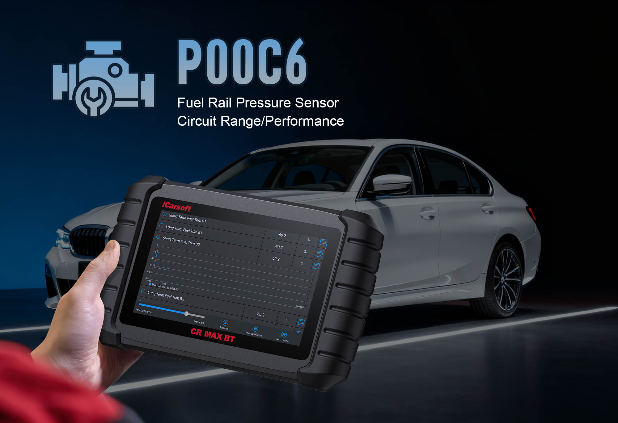
Diagnose & Clear P00C6 with iCarsoft CR MAX BT
If your vehicle’s check engine light illuminates, you notice erratic engine temperature gauges, or it struggles with overheating or poor cold-start performance, a diagnostic scan will likely return P00C6. This OBD-II code stands for "Coolant Temperature Sensor Circuit High Voltage – Bank 1, Sensor 2"—a fault targeting the secondary engine coolant temperature (ECT) sensor. The secondary ECT sensor is usually mounted in the radiator, coolant hose, or cylinder head on cylinder bank 1.
The ECT sensor measures coolant temperature to help the Engine Control Module (ECM) adjust fuel injection, fan operation, and ignition timing. When it sends abnormally high voltage signals, the ECM uses incorrect temperature data, leading to inefficient combustion, overheating risks, and reduced engine lifespan. Basic scanners can’t isolate faults, but the iCarsoft CR MAX BT with specialized diagnostics solves this. Let’s break down how to resolve P00C6 step by step.
Understanding P00C6: Symptoms & Causes
The Bank 1, Sensor 2 ECT sensor works with the primary ECT sensor (Sensor 1) to provide redundant temperature data. It uses a thermistor—resistance decreases as coolant temperature rises, and voltage drops accordingly. P00C6 triggers when the ECM detects circuit voltage above the manufacturer’s threshold (typically >4.5V), indicating an open circuit or unresponsive sensor.
Key Symptoms of P00C6
-
Illuminated Check Engine Light (CEL): A steady CEL turns on, and some vehicles display "Coolant System Warning" or "Engine Overheating Risk" on the dashboard.
-
Erratic Temperature Gauge: The gauge may stick at "cold" (even when the engine is warm) or jump to "hot" unexpectedly, masking real overheating issues.
-
Poor Cold Starts: The ECM thinks coolant is colder than it is, leading to overfueling—causing rough idling, hesitation, or difficulty starting in mild weather.
-
Overheating Risk: The sensor fails to detect rising coolant temperature, so the ECM doesn’t activate the cooling fan—risking engine overheating and damage.
-
Reduced Fuel Efficiency: Incorrect temperature data disrupts air-fuel ratios, dropping mileage by 10–15% and increasing emissions.
Common Causes of P00C6
|
Cause
|
Description
|
|
Faulty ECT Sensor
|
The thermistor inside Bank 1, Sensor 2 fails (from extreme temps or coolant leaks), sending high-voltage signals.
|
|
Damaged Circuit Wiring
|
Frayed wires, rodent chew marks, or corrosion in power/ground lines create an open circuit, leading to high voltage.
|
|
Loose/Corroded Connector
|
The sensor’s 2–3 pin connector (near radiator/cylinder head) becomes loose or rusted (from coolant leaks), breaking the connection.
|
|
Blown ECT Sensor Fuse
|
A dedicated "ECT Sensor" or "Coolant Temp" fuse in the under-hood box blows, cutting power to the circuit.
|
|
Coolant Leaks
|
Leaking coolant damages the sensor’s connector or internal components, disrupting signal transmission.
|
|
ECM Malfunction
|
Rarely, the ECM’s internal ECT monitoring circuit fails, incorrectly detecting high voltage.
|
Why iCarsoft CR MAX BT Excels at Diagnosing P00C6
The CR MAX BT outperforms basic tools with features tailored to ECT sensor circuit diagnostics—critical for safety. Here’s its key value:
Wireless Bluetooth Connectivity
Test hard-to-reach Bank 1, Sensor 2 (near radiator/engine block) from 30 feet away—no cords hinder access to hot under-hood areas.
Live Voltage & Temp Tracking
Monitors real-time voltage (0.5V–4.5V normal) and temp (100–220°F) — highlights high-voltage issues (>4.5V) instantly.
Sensor Resistance Tests
Built-in multimeter checks thermistor resistance, verifying if the sensor responds to temperature changes (hot vs. cold coolant).
Cooling Fan Bi-Directional Tests
Sends direct commands to activate the cooling fan—verifies ECM response and prevents overheating risks.
AutoVIN Identify
Automatically detects vehicle make/model and ECT specs (voltage range, pinouts) in seconds—no manual lookup.
Step-by-Step: Diagnose & Clear P00C6 with iCarsoft CR MAX BT
-
Prior Safety Check & Visual Inspection
1. Check coolant level: Ensure engine is cool, open reservoir—level should be between "Min"/"Max"; add recommended coolant if low. Look for leaks.
2. Locate the sensor: Use Component Location > Engine > Cooling System > ECT Sensor (Bank 1, Sensor 2) (Bank 1 = cylinder #1 bank; Sensor 2 = secondary).
3. Inspect connector: Remove (gloves if warm), check corrosion/bent pins—clean with contact cleaner, apply dielectric grease.
4. Inspect wiring: Follow harness to ECM, check frays/heat damage—repair with heat-shrink; replace if severe.
5. Check ECT fuse: Use Fuse Guide to locate/test—replace if blown.
-
Connect the Tool & Confirm P00C6
Plug CR MAX BT into OBD-II port, power on, select AutoVIN Identify to retrieve specs. Navigate to Engine > Fault Codes > Read Codes to confirm P00C6. Tap Code Details for vehicle-specific insights (e.g., "Toyota Camry: ECT High Voltage; Expected 0.5–4.5V, Actual 5.0V"), and check related codes (e.g., P00C5, P0117).
-
Monitor Live ECT Sensor Data
Start engine, idle 10 minutes (warms coolant). Navigate to Engine > Live Data > Coolant Temperature > Bank 1, Sensor 2:
- Voltage: Should drop from ~4.5V (cold, 60°F) to ~0.5V (hot, 220°F); >4.5V confirms P00C6.
- Temp reading: Compare to primary ECT (Bank 1, Sensor 1) and gauge—stuck "cold" = faulty sensor.
- Fan test: Rev engine to warm coolant (~200°F)—ECM should activate fan; no activation = use bi-directional test (step 5).
-
Test ECT Circuit Integrity
Turn off engine, disconnect sensor (ensure cool):
1. Power wire test: Set multimeter to "DC Voltage"—touch power pin ("V+" in pinout) + ground. Ignition "ON" = 5V/12V (vehicle-dependent); 0V = blown fuse/broken wire.
2. Ground wire test: Set to "Ohms"—touch ground pin ("GND") + chassis ground. Normal = <1 ohm; >5 ohms = poor ground.
3. Signal wire test: Check continuity between signal pin and ECM (use wiring diagram)—no continuity = broken wire.
-
Test the ECT Sensor & Cooling Fan
1. ECT resistance test: Remove sensor (use Component Removal Guide, torque 8–10 ft-lbs):
- Cold test (70°F): 2–10 kOhms (check Sensor Specs);
- Hot test (180°F): Submerge tip in hot water 2 mins—resistance drops to 0.5–2 kOhms; no change = faulty.
2. Fan bi-directional test: Reconnect sensor, navigate to Special Functions > Engine > Cooling Fan Control—command "Low/High Speed"; fan should activate; no response = fan motor/relay issue.
-
Repair & Clear P00C6
- Blown fuse/leaks: Replace fuse with OEM-compatible one; fix leaks with clamps or new hoses.
- Wiring/connector: Repair frays; clean connectors with dielectric grease (coolant-resistant).
- Faulty sensor: Replace with OEM-equivalent (use Part Lookup—e.g., Bosch 0280130047 for GM, Denso 234-0002 for Toyota); torque to specs, refill coolant.
- ECM malfunction: Consult dealer for reprogramming/replacement (last resort).
Clear code: Go to Engine > Fault Codes > Clear Codes to delete P00C6.
-
Validate Repair & Ensure Safety
1. Monitor data: Start engine—confirm voltage drops 4.5V→0.5V as coolant warms, temp matches gauge.
2. Fan test: Idle until coolant ~200°F—verify fan activates automatically.
3. Test drive: Operate 30 minutes (highway + idle)—ensure CEL stays off, gauge stable.
4. I/M Readiness Test: Run via OBDII Functions for emissions compliance.
5. Save report: Use History & Report to store diagnostic data (track coolant system health).
Preventing P00C6 Recurrence
-
Regular Sensor Checks: Use Service Reminder to test Bank 1, Sensor 2 every 30,000 miles—catch thermistor wear early.
-
Coolant Maintenance: Check coolant level/condition every 15,000 miles; replace every 2–3 years (per manufacturer) to prevent corrosion.
-
Wiring Protection: Inspect harness every 15,000 miles for rodent damage/heat wear—use heat-resistant loom near the engine.
-
Lifetime Free Updates: Use One-Key Upgrade (Wi-Fi) to add new ECT diagnostic features.
Conclusion
P00C6’s high-voltage ECT sensor fault isn’t minor—it risks engine overheating and long-term damage. The iCarsoft CR MAX BT simplifies diagnosis with wireless convenience, live tracking, and fan tests, ensuring you fix the root cause (not just the symptom). Whether you’re a DIYer or pro, this tool prioritizes safety and accuracy.
With global vehicle coverage and 40+ service functions, the CR MAX BT is a long-term investment in protecting your engine. Restore reliable coolant temperature monitoring, avoid overheating, and drive with confidence—all with one professional-grade diagnostic tool.