Diagnose & Clear P2127 with iCarsoft CR MAX BT: Fix Throttle/Pedal Position Sensor/Switch E Circuit Low Input
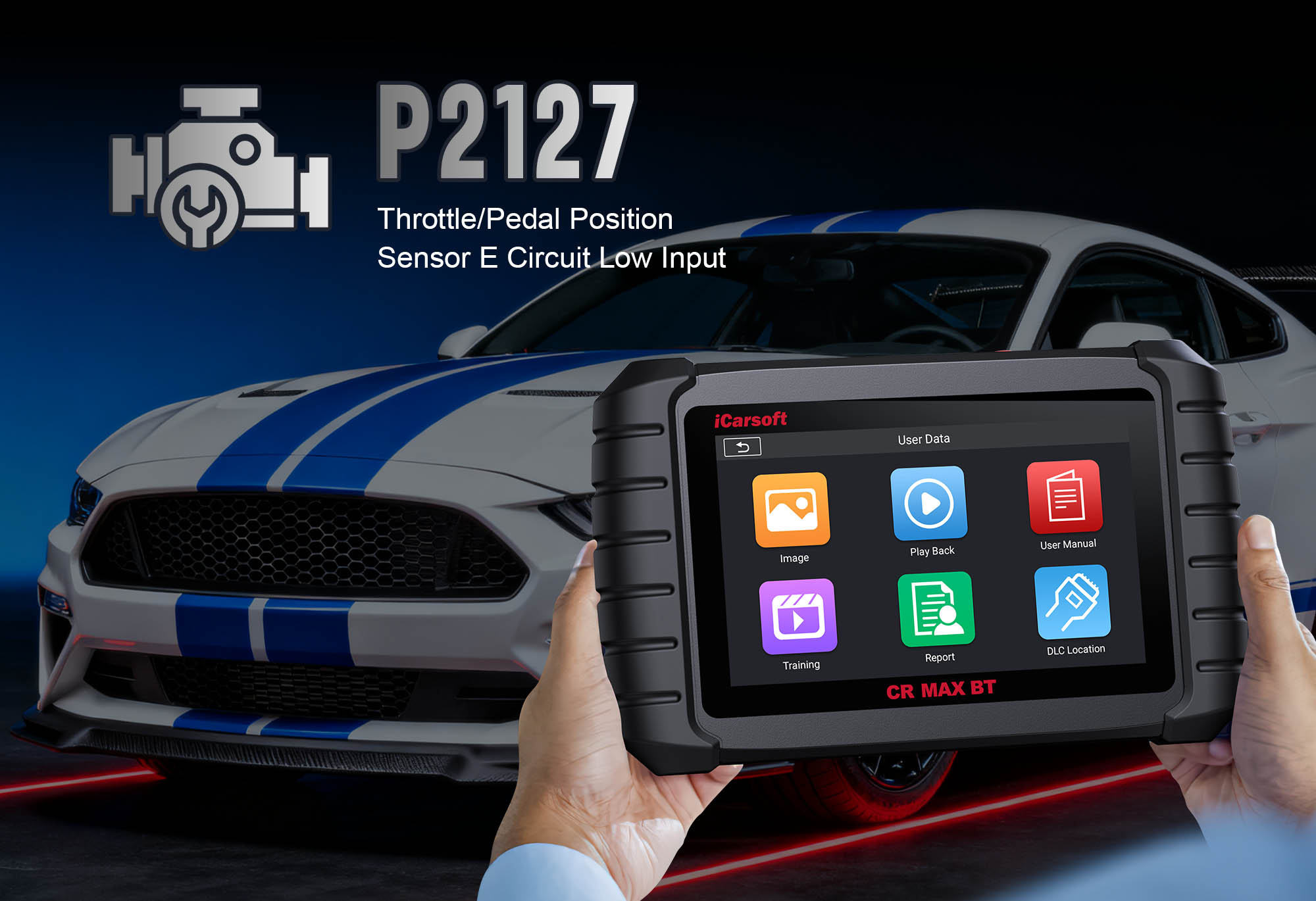
Diagnose & Clear P2127 with iCarsoft CR MAX BT
If your vehicle’s Check Engine Light illuminates, you experience unresponsive acceleration, or the engine enters "limp mode" (capping speed to protect components), a diagnostic scan will likely return P2127. This OBD-II code stands for "Throttle/Pedal Position Sensor/Switch E Circuit Low Input"—a fault targeting the electronic throttle position sensor (TPS) or accelerator pedal position (APP) sensor’s "E" circuit.
These sensors communicate acceleration intent to the Engine Control Module (ECM); the "E" circuit is a redundant signal path that prevents total throttle loss. When its voltage drops below the manufacturer’s minimum (typically 0.2V–0.5V), the ECM can’t trust throttle data, triggering limp mode. Basic scanners only flag a "throttle sensor issue," but the iCarsoft CR MAX BT with specialized throttle diagnostics solves this. Let’s break down how to resolve P2127 step by step.
Understanding P2127: Causes & Key Symptoms
Modern vehicles use TPS (mounted on the throttle body, measuring valve opening) or APP sensors (mounted on the pedal, measuring travel)—or both for redundancy. The "E" circuit sends voltage that scales with movement (0.5V at idle, 4.5V at wide open). P2127 triggers when the ECM detects "E" circuit voltage <0.2V for 5–10 seconds, indicating a circuit break or sensor failure.
Key Symptoms of P2127
-
Check Engine Light (CEL): A steady CEL illuminates, often paired with "Throttle Sensor E Circuit Low" or "Limp Mode Active" on the dashboard.
-
Unresponsive Acceleration: Pressing the accelerator has little effect, or the engine hesitates before speeding up.
-
Limp Mode Activation: ECM limits power to ~50% (capping speed at 30–40 mph) to prevent unintended throttle behavior.
-
Engine Stalling: At low speeds (e.g., stop signs), the engine may stall if the ECM can’t detect stable idle throttle position.
-
Erratic Idle: Engine idles roughly or fluctuates (500–1,000 RPM) as the ECM struggles with unreliable throttle data.
Common Causes of P2127
|
Cause
|
Description
|
|
Faulty TPS/APP Sensor
|
Internal wear or corrosion in the "E" circuit resistor drops voltage below threshold—common after 80,000–120,000 miles.
|
|
Damaged Wiring/Circuit
|
Frayed wires, rodent chew marks, or corrosion create an open connection, dropping "E" circuit voltage to near 0V.
|
|
Loose/Corroded Connector
|
Sensor’s 4–6 pin connector (near throttle body/pedal) is loose, rusted, or oil-contaminated—disrupting "E" circuit signals.
|
|
Throttle Body Carbon Buildup
|
For TPS-equipped vehicles, carbon deposits stick the throttle plate closed, forcing the "E" circuit to report false low voltage.
|
|
ECM Malfunction
|
Rarely, the ECM’s internal "E" circuit processing fails, misinterpreting normal voltage as "low input."
|
Why iCarsoft CR MAX BT Excels at Diagnosing P2127
The CR MAX BT outperforms basic tools with features tailored to throttle/pedal position sensor diagnostics—critical for resolving P2127 accurately:
Wireless Bluetooth Connectivity
Test TPS (under hood) or APP sensor (under dashboard) from 30 feet away—no cords hinder access to hard-to-reach components.
Live "E" Circuit Voltage Tracking
Monitors real-time "E" circuit voltage (and other redundant circuits) to flag low input (<0.2V) and compare to expected values.
Sensor Redundancy Checks
Distinguishes "E" circuit faults from power/ground issues (only "E" low = sensor/circuit; all circuits low = power problem).
AutoVIN Identify
Automatically detects sensor type (TPS/APP), "E" circuit voltage range, and pinouts—eliminates manual engine diagram lookup.
Bi-Directional Throttle Tests
Sends commands to activate the throttle body, verifying if the "E" circuit responds to movement—rules out mechanical sticking.
Step-by-Step: Diagnose P2127 with iCarsoft CR MAX BT
-
Safety First & Initial Visual Inspection
1. Disconnect battery: Turn off ignition, remove negative terminal (wrench) to avoid accidental throttle activation.
2. Locate sensor (TPS/APP): Use Component Location > Engine > Throttle System—TPS on throttle body, APP on accelerator pedal.
3. Inspect for issues:
- Wiring: Follow "E" circuit wire (from Wiring Diagram) for frays, chew marks, or corrosion.
- Connector: Disconnect, check for bent pins/rust; clean corrosion with contact cleaner.
- Throttle body (TPS): Remove air intake, inspect for carbon buildup (black sooty deposits) on the plate.
-
Connect Tool & Confirm P2127
Reconnect battery, plug CR MAX BT into OBD-II port, select AutoVIN Identify to retrieve specs. Navigate to Engine > Fault Codes > Read Codes to confirm P2127. Tap Code Details for vehicle-specific insights (e.g., "Ford: APP Sensor E Circuit; Expected 0.5–4.5V, Actual 0.1V"). Check related codes (P2122, P2123, P2128) and resolve P2127 first.
-
Monitor Live "E" Circuit Data
1. Start engine, idle 5 minutes to stabilize (don’t touch accelerator).
2. Navigate to Engine > Live Data > Throttle/Pedal Position; monitor Bank 2 metrics:
- Idle Voltage: Normal = 0.2V–0.5V; P2127 shows <0.2V.
- Acceleration Voltage: Press accelerator slowly—should rise to 4.0V–4.5V; stuck/dropping = "E" circuit issue.
- Redundant Circuits (A/B/C): Compare to "E"—only "E" low = sensor/circuit; all low = power/ground problem.
3. Limp mode test: Accelerate—note voltage drop when limp mode activates (confirms ECM reacts to low input).
-
Test "E" Circuit Integrity & Sensor Function
1. Circuit voltage test: Turn off engine, disconnect sensor; set multimeter to "DC Voltage"—"E" pin + power pin (ignition "ON") = 5V (0V = broken wire/fuse).
2. Ground test: Set to "Ohms"—sensor ground pin + chassis = <1 ohm (>5 ohms = clean ground strap).
3. Bi-directional test: Reconnect sensor; navigate to Special Functions > Engine > Electronic Throttle Control > Sensor Activation; select "E Circuit"—normal voltage rise/fall = good sensor.
4. Throttle body cleaning: Spray throttle body cleaner on plate/bore, wipe with lint-free cloth; reinstall air intake.
-
Repair or Replace Sensor/Circuit
- Wiring: Use heat-shrink for frays; splice broken wires with OEM-grade crimp connectors; replace severely damaged harnesses.
- Sensor replacement: Remove old TPS/APP (torque: TPS 6–8 ft-lbs, APP 4–6 ft-lbs); install OEM part (e.g., Bosch 0280122051 for TPS); apply dielectric grease to connector.
- ECM reset: Use Special Functions > Engine > Control Unit Reset; install firmware updates via One-Key Upgrade for persistent issues.
-
Calibrate & Clear P2127
1. Sensor relearn: Run Special Functions > Engine > Electronic Throttle Control > TPS/APP Relearn; follow prompts (e.g., "Turn key ON, wait 10s, press accelerator wide open").
2. Clear code: Navigate to Engine > Fault Codes > Clear Codes—confirm P2127 is deleted. Start engine, verify CEL stays off.
-
Validate the Repair
1. Post-repair check: Idle/accelerate to confirm "E" circuit voltage stays 0.2V–4.5V (no drops).
2. Test drive (30–40 minutes): Check smooth acceleration, no limp mode, and stable idle.
3. Redundancy test: Use Live Data to confirm all throttle circuits (A/B/C/E) sync with acceleration.
4. Save report: Document fault/repairs via History & Report.
Preventing P2127 Recurrence
-
Regular Sensor Checks: Use Service Reminder to test TPS/APP circuits every 30,000 miles—catch early voltage drops.
-
Throttle Body Maintenance: Clean throttle body every 60,000 miles (TPS vehicles) per Maintenance Schedule—prevents carbon buildup.
-
Wiring Protection: Inspect "E" circuit wiring every 15,000 miles for rodent damage/heat wear; use abrasion-resistant loom.
-
Lifetime Updates: Use One-Key Upgrade to add new throttle diagnostic features (e.g., advanced circuit tracing).
Conclusion
P2127’s "E" circuit low input isn’t just an acceleration issue—it risks limp mode or unresponsive throttle. The iCarsoft CR MAX BT simplifies diagnosis with wireless convenience, live voltage tracking, and sensor tests—ensuring you fix the root cause (faulty sensor, wiring, or carbon buildup) instead of guessing.
With global vehicle coverage, 40+ service functions, and lifetime updates, the CR MAX BT is a long-term investment in throttle reliability. Restore responsive acceleration, eliminate limp mode, and drive with confidence—all with one professional-grade tool.